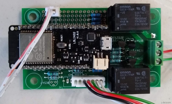
Circuit Design for ESP32 Interface
Input Interfaces
Measuring 12 volt signals
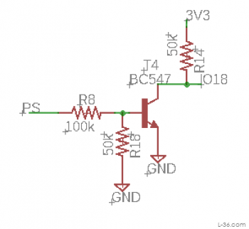
There are several 12 volt signals we want to detect. The goal here is are the signals there or not. Is the pump running, is the main power switch on. We are not trying to measure the voltage, just see if they are on or off. The input voltage to the ESP32 needs to be below 3.3 volts or it will be destroyed so we need a way to interface to go from something in the 10 to 14 volt range to a logic level of high (3.3 volts) or low (ground). I did that with a switching transistor. These transistors cost 15 cents and the resistors are 5 cents so this is not an expensive circuit. The resistor R8 will supply enough current from a 12 volt signal to drive the transistor into saturation, in other words, switch on. The resistor R18 makes sure that a small glitch will not turn on the transistor. The pull up resistor R14 is only necessary for the input that is used to wake the ESP from sleep. For an input that is just being read after the unit is awake, the ESP input can be set to use an internal pull up. But these do not work with the unit sleeping so in that case an external resistor is required.
Measuring voltage
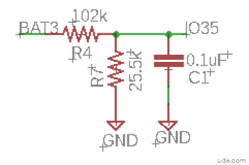
This circuit, and some of the software, is all about overcoming the limitations of the ESP32 ADC function. The most obvious limitation is that the input needs to be less than 3.3 volts. This circuit will divide the input voltage by exactly a factor of 5. That will allow measurements up to 16.5 volts. The next limitation is noise. The ADC is extremely noisy. The capacitor helps with filtering external noise but there is noise that comes from the circuit itself. Also, we are trying to measure fractions of a volt. A battery is basically dead at 12 volts and fully charged at 12.6 so the entire range of what we are trying to measure is under 4% of the measurement range. To get a valid reading I employed several strategies. Simple averaging was not going to work because the noise was not gaussian as there were random spikes that needed to be rejected. The lowest level reading takes 8 readings and tosses the highest and lowest and divides by 6. Then 100 of these readings are taken and averaged. In total I average 600 readings and ignore 200. This produces a very stable reading but it is still not very accurate.
It isn't accurate because the ADC is notoriously non linear. I took readings at various points in the region I cared about and did a third order curve fit. Finally there is a gain term as there is also variation unit to unit and I have three units so I can swap out one and program it at home. This gain term will adjust the reading so they are right at one point, which I set to be the most important point. With the linearization, they are very close over the entire range I care about.
Controlling the relay
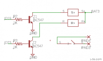
I used more transistors to switch the relays. A simple 1,000 ohm resistor is used to limit the current into the base. The coil current is 23mA and we want about 2.3mA into the base. The 1K resistor gives 2.6mA which is fine. The transistor drives the relay coil to ground with the other end connected to the battery. The specifications on the relay allow 8.4 to 19.2 volts which is more than enough tolerance. The ESP32 only needs to supply current for 20mS so this is not a big drain on the battery. The relays I used are rated at 10Amps, more than enough. The fan has a 1 Amp fuse and the small pump a 5 Amp fuse. As I said, these are latching relays so there is an input to close the relay and one to open it and power does not need to be applied except to change the state. Lifetime on these relays operated once a day would be 500 years.
NEXT⇨
NOTICE: Some pages have affiliate links to Amazon. As an Amazon Associate, I earn from qualifying purchases. Please read website Cookie, Privacy, and Disclamers by clicking HERE. To contact me click HERE. For my YouTube page click HERE