Technical Information on Block Systems
Purchase Ratios / Purchase Systems
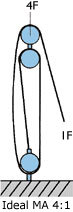
Mechanical advantage can be achieved by using a purchase system as seen in the diagrams below.
 |
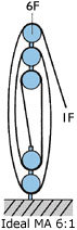 |
(this is often referred to as the Purchase of the System)
The mechanical advantage of the system is always slightly less than the velocity ratio or purchase due to friction losses. In an ideal system (100% efficiency) the mechanical advantage = velocity ratio.
Block Loadings and Human Input
All the various sail control systems on board a boat have a common problem, they are powered by human muscles (with the exception of the latest electric or hydraulic push button winches).
For example a small boat of 20ft (6.0m) jib could be easily trimmed, whereas a 50ft (15.2m) cruising yacht may require 5,000 lbs (2,250kg) of trimming force in a blow, but regardless of boat size the trimming engine is the same: a human being.
Today small crews often operate large yachts therefore efficient use of manpower for sail trimming is imperative.
The average forces a man can exert are as follows-| i) | Pull directly downwards from above a force directly equivalent to his body weight. | |
| ii) | Pull horizontally standing up with feet braced, approx. 75lbs (34Kg) with both hands and 50lbs (23kg ) with one hand. | |
| iii) | When pulling control lines such as the mainsheet traveller he can comfortably handle loads of 25 to 35lbs (11 to 16kg). |
And so, since human force is limited to a small pulling power, and the loadings sails create can be enormous, a mechanical advantage must be applied through Block Systems and Winches, to allow a sailor to correctly control sail trim.
Friction
Mainsheet system showing losses due to friction
(assuming an allowance per block of 2.5%, using roller bearings).
Whilst pulling the mainsheet in, friction requires more input and increases the load on the input blocks.
Cascade Systems
Cascade System used on Kicking Strap
These are ideal for applications where fast response with relatively small movement is required, giving high power purchases, as each purchase acts as a multiplier.
Coarse and Fine Tune Purchase Mainsheet Systems
These systems are usually used on racing boat mainsheet systems.
The system comprises:
Coarse System.
This is used for hauling in the mainsail, especially after a gybe when mark rounding. This coarse purchase system say 5:1 can cater for such large adjustments.
Fine Tune System.
This system is used for the constant final adjustment of the mainsail when sailing to windward, especially in gusty conditions. This fine tune system has a higher purchase say 20:1.
Alignment of Blocks
Special care must always be taken that the block is allowed to lie in the same plane as the sheet otherwise wear will occur or even an overloading of the block due to the imposed torque.
Safe Working Loads on Blocks and Footblocks
The safe working load is the maximum load at which a block or footblock should be operated. It is important to look at each block individually because if it is part of a system it might not relate directly to the actual load being pulled.
There is another factor involved in block loading. This is the change of angle the rope turns through - the angle between the line of entry and the lines departing direction after passing around the sheave. Once the line starts to bend around the sheave, the total load on the sheave starts to increase until at 180 degrees the maximum sheave loading is reached, ie. see from the chart if a rope turns 180 degrees around the sheave and the rope has a tension of 10lb (4.5kg) the total sheave load is increased by a factor of 2 = 2 x 10lb (9kg) total sheave load.
Deflection Loads
| Change of Angle | Load Factor |
Change of Angle | Load Factor |
Change of Angle | Load Factor |
||
| 180° | 2.00 | 120° | 1.73 | 50° | 0.84 | ||
| 170° | 1.99 | 110° | 1.64 | 45° | 0.76 | ||
| 160° | 1.97 | 100° | 1.53 | 40° | 0.68 | ||
| 150° | 1.93 | 90° | 1.41 | 30° | 0.52 | ||
| 140° | 1.87 | 80° | 1.29 | 20° | 0.35 | ||
| 135° | 1.84 | 70° | 1.15 | 10° | 0.17 | ||
| 130° | 1.81 | 60° | 1.00 | 0° | 0.00 |
Choice of Bearing
For lines requiring rapid adjustment whilst under high load i.e. mainsheet, headsail, halyards and traveller systems, use should be made of roller or ball bearings in order to keep friction losses to a minimum. Applications where plain bearings are adequate include spinnaker pole uphauls/downhauls, main halyards, runner blocks.
See graph comparing efficiency of roller bearings and plain bearings.
Genoa Sheet Deflection Through Genoa Cars
It is worth noting that the Genoa No. 1 and No. 3 require different vertical sheeting angles. As the vertical sheeting angle for the No. 3, approximately 70 degrees is greater than the No. 1, the loads on the No. 3 Jib car can be greater than the No.1 Genoa car.
The effort required to tow a Genoa car under load changes dramatically with the vertical sheeting angle. A No 3 blade jib will have a large sheeting angle, up to 70 deg. with the correspondingly high tow load of 65% of the sheet load. A no 1 Genoa may be as low as 40 deg. with a tow load of only 25%. When specifying the tow purchase care must be taken to match the equipment with the anticipated loads, use the following table as a guide.
Genoa Car Towing Loads
Offset Loads on Mainsheet Cars
Typically the breaking load is reduced when the mainsheet load is offset. If you are in any doubt as to the suitability of selection contact your Lewmar subsidiary.
Mainsheet towing loads
As a guide, mainsheet towing loads are 25% of the total sheet load.
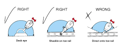
Snatch Block use
Where a snatch block is attached in a situation which will not permit full movement, such as through some toe rails, a shackle must be used to ensure full articulation.
Rope Clutch Holding Loads Explained
The holding load of each clutch is listed for the two main line sizes the clutch was designed to hold , the maximum and minimum listed are dependent on the line type used.
Rope clutches can handle one line size below the nominal range but at a reduced holding load, this can be usefull for more lightly loaded applications such as control lines and down hauls. In virtually all cases the larger the line the better the holding capacity, so where the ultimate load is required the larger of the designated line should be used.
These graphs show the range of holding loads that can be achieved, a good quality hard cored line will hold better than a softer line, in some cases this may be higher than the rated Safe Working Load of the clutch but in all cases the line will slip before the Breaking Load is reached.
D1 Rope Clutch
D2 Rope Clutch
NOTICE: Some pages have affiliate links to Amazon. As an Amazon Associate, I earn from qualifying purchases. Please read website Cookie, Privacy, and Disclamers by clicking HERE. To contact me click HERE. For my YouTube page click HERE