Line and Rigging
Blocks and Mechanical Advantage
Introduction
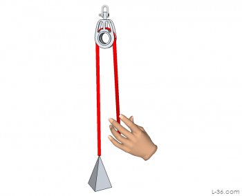
This is the first part of a two part tutorial on mechanical systems made from blocks and line. The second part is HERE. I will explore the mechanical advantage of various systems, and shows the general principles on how to set these systems up, including how to thread the line through the blocks, or reeve them. It will go from 1:1 to 6:1 with simple systems and up to 24:1 with cascaded systems. The second part will explore some more unusual systems.All block systems are comprised of a stationary part and a moving part. These terms are self explanatory. Most all tutorials on block systems show the fixed part at the top and the moving part, attached to some weight, at the bottom. In other words, they are systems that lift a load. It is left to the reader to realize these can be turned around and used to pull down. On a boat, the majority of block systems pull down. These include the mainsheet, vang, and Cunningham. For that reason, I am detailing systems that pull down as well as the more conventional diagrams that pull up. Some block systems pull sideways for example outhauls and reef systems. For those you can decide which drawing is most appropriate to your application.
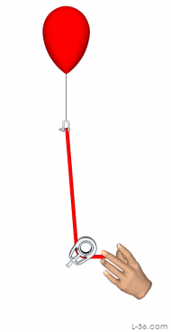
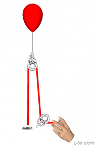
Creating the diagram of a system that pulls up was a bit of a challenge. I needed something that represented an upward force and a weight of course always pulls down. What I decided to use was a super anti gravity filled balloon. This anti gravity gas pulls up with a force just as strong as the downward force supplied by the weight on the drawings. In use, you can replace my anti gravity gas balloon with your mast or sail.
Mechanical Advantage (Purchase)
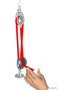
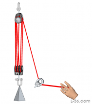
If, on the other hand, the weight at the bottom is an anchor point that does not move, and the system is pulling down on a anti gravity filled balloon connected to the upper block to lower it, then you have a 2:1 mechanical advantage. If the upper block is 10 feet above the ground there would be 10 feet or line going up to the block and 10 feet of line going back down to the hand doing the pulling on the ground. To move the block down 10 feet, you would have to pull down 20 feet of rope.
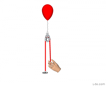
The work done by the hand and the work down on the block moving down must be the same. Assume it takes 10 pounds of force to move the balloon. In other words, the balloon could just lift a 10 pound weight. If the block moves down 10 feet, you have done 100 foot pounds of work or 100 ft-lb. To do this work, you pulled in 20 feet of line. Since the work is the same, the force it must have taken to do this 100 ft-lb or work is 5 pounds. Thus you have pulled down a 10 pound force using 5 pounds of effort. This gives you a 2:1 mechanical advantage. You can always determine the mechanical advantage by measuring how much line you have to pull and divide that by the amount the load moves.
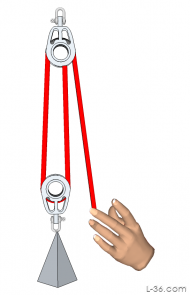
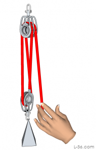
Count the number of lines that are attached to the moving part
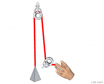
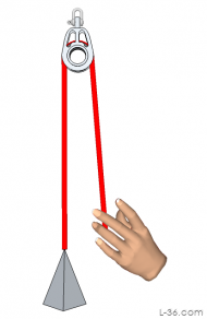
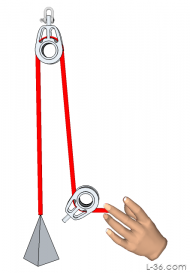
In the first example, only the line from the block to the weight moved as the weight moved up. For every foot you pull the weight up, you pull one foot of line down. This is a 1:1 system and there is one line attached to the moving part. When we are pulling the anti gravity balloon down, there are two lines attached to the moving part so the mechanical advantage is 2:1. You can see that if the anti gravity balloon was 10 feet above the ground that there would be 20 feet of line, one line going up and the other going down. If you pull the balloon down to the ground and there is no line going to or from the moving part, then you would have pulled 20 feet of line, again a 2:1 system. You can always determine the mechanical advantage by counting the number of lines that to to the moving part.Bosom Chair Example
Go back to the first picture where we are moving the weight. This is a 1:1 system. But what if we were the weight and were pulling ourselves up the mast, for example. In that case, we become part of the moving part so there are now two lines moving. This would then be a 2:1 system. But if the same system were pulled by your friend on the ground, there would only be one line attached to the chair. In other words, the same system if pulled from the ground would be a 1:1 system, but if pulled from the chair it would be a 2:1 system. If you add a block to the chair and terminate the line on a becket on the upper block, it would be a 2:1 system from the ground and a 3:1 system when pulling from the chair.Turning Blocks
A Note on Beckets
A becket is a tab on a block used to terminate the line. Many of the systems I am showing have beckets. Unfortunately I did not draw the becket but rather just mysteriously have the line end either on the block or close to it. Please use your imagination to envision a becket on the block. You will see this first on the 2:1 systems pulling up.Block Systems
| down | down w/turn | up | up w/turn | |
| 1:1 | 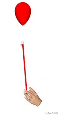 |
 |
 |
 |
| 2:1 | 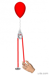 |
 |
 |
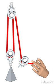 |
| 3:1 | 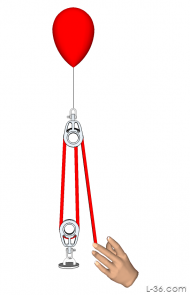 |
 |
 |
 |
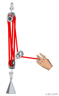
Cross Reeving
4:1 Systems

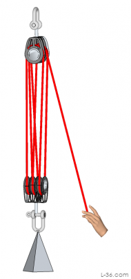
Fiddle Blocks
Higher Order Systems
| down | down w/turn | up | up w/turn | |
| 5:1 | 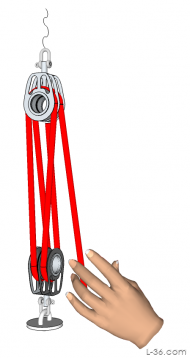 |
 |
 |
 |
| 6:1 | 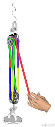 |
 |
 |
 |
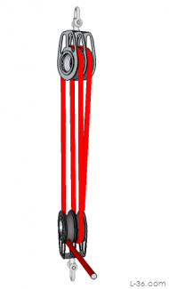
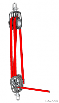
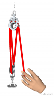
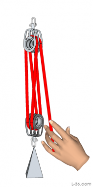
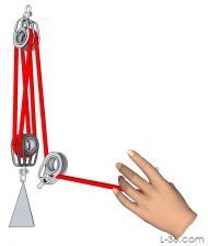
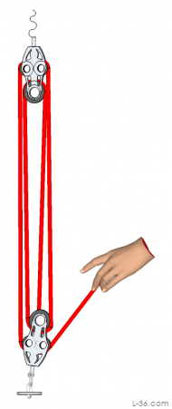
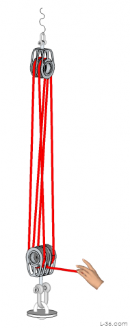
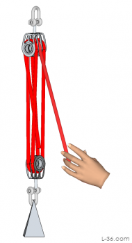
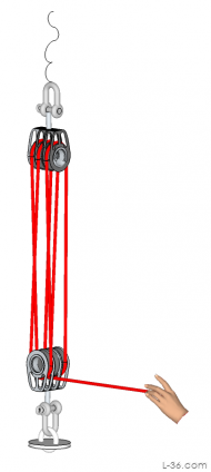
Triple Blocks
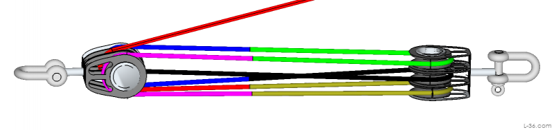
The reeving I have shown with triple blocks always has the tail coming out the center. That makes the load balanced so there is no twist from the end that leaves the block. The picture above uses colors to make it easier to see where the lines go.
NOTICE: Some pages have affiliate links to Amazon. As an Amazon Associate, I earn from qualifying purchases. Please read website Cookie, Privacy, and Disclamers by clicking HERE. To contact me click HERE. For my YouTube page click HERE