Line and Rigging
More Low Friction rings
Part 2 of series on low friction rings
By Allen Edwards
Introduction
In the first article of this series we gave results on using fairleads and showed how the added friction is not significant with low deflection angles. In this article we consider using low friction and other standard rings with high deflections and analyze how these can be used in systems to provide simple and inexpensive mechanical advantage. Again we used the digital scale shown on the right to make the measurements. This scale reads up to 220 pounds with 1/2 pound resolution. One nice things about the scale is that it has a peak hold function so the test can be made without constantly looking at the readout as the peak can be read at the end.The test data below was made with 1/8 inch Amsteel and a number of different rings. There was a fair amount of variation in the readings particularly as the Amsteel set to the ring. For example, one set of measurements read 54.5, 53, 51, 51 in four readings and settled on 51. For this to happen, something has to change in the material of the line and what changed was the line flattened and took a set to the ring. Once that happened, the variation in the readings went away. I tried using different diameters of line but found the variation line to line was not explainable by diameter alone so did not draw conclusions about the effect of line diameter. The major conclusions would not change as we still learned a great deal using the 1/8 Amsteel.
Test Setup
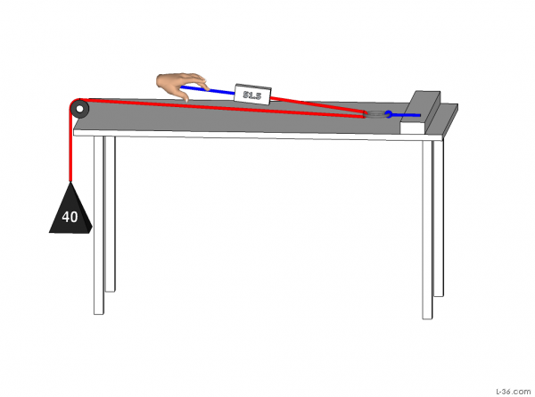
The test bench used a 40 pound weight hung over the edge through a Garhauer block. Measurements were taken with the digital scale discussed in the introduction.
Rings Tested
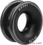
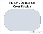
The other two rings were Antal low friction rings. One the 20x14 and the other the 14x10. Both are very nice products and highly recommended although the $5 ring from REI works just as well. They are all light with the smaller Antal at 1/2 oz. The Omaga was 1.2 oz and the larger Antal 1.5 oz. and all much lighter than the 3 1/4 oz of the stainless steel ring. The diameters of the working surface ranged from 9mm for the SS ring to 22mm for the larger Antal. The Omega was 11mm and the smaller Antal 15mm.
Cross Sections
Test Results
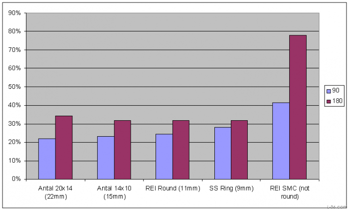
I would consider the differences between the various round rings noise. The average loss from a 90 degree bend was 24% and from a 180 degree bend 32%. Notice however that the loss from the SMC ring was much higher.
A Simple One Part System
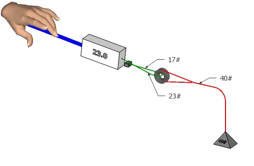 The system above is a simple "2:1" system. To analyze what the mechanical advantage is consider the pulling force required to lift the 40 pound weight. We know the loss through the ring is 32% so the force you pull on the line is 1.32 times the force delivered to the other side of the line you are pulling on with the rest of the force lost in friction. Both these forces pull on the ring meaning that the load sees 2.32 times the force on the anchored ring. The pulling side is 1.32 times the anchored side so the mechanical advantage is 2.32 / 1.32 or 1.75:1, just under the 2:1 frictionless case. In the example above, the pull is 23# and the anchored side sees 23# / 1.32 or 17#. The total pull is then 23 + 17 = 40 pounds. (There is some rounding in this example).
Cascaded Systems
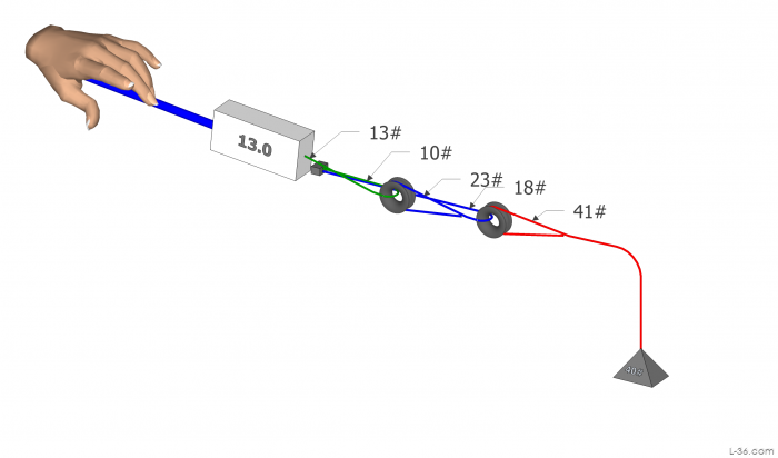
To check this and to serve as another example I built the system above and measured the pull required to pull my 40 pound weight up. It was exactly 13 pounds just like the theory from the measurements would say. This "4:1" system is 3.1:1 which is just what you would expect from a cascaded system where the individual blocks are 1.76:1. Please note that there is a small loss in the Garhauer block (not shown) so that there is really 41 pounds required to lift the 40 pound weight.
NOTICE: Some pages have affiliate links to Amazon. As an Amazon Associate, I earn from qualifying purchases. Please read website Cookie, Privacy, and Disclamers by clicking HERE. To contact me click HERE. For my YouTube page click HERE