How to Calculate the Dimensions of a Wedge Pad for a Foot Block Turning Block
By Allen Edwards
(Spoiler alert: There is a calculator click here so you will not have to make these calculations. You will have to understand what you are trying to do to use the calculator, however, so you will need to read the following anyway).
I recently decided to add a foot block to take the line from the rail car back to the foot block where it turns almost 180 degrees and then forward to my main winch. I considered using a block on a car on the rail but did not want to put the added stress on the rail. In addition, the places I wanted to put the block had stations in the way. I decided on a 7 inch Garhauer block but needed a pad under it that was wedge shaped to give fair lead angles to the jib sheet coming both from the car and going to the winch. This turned out to be a real mind teaser so I thought it would be a good idea to write it down so that others would not have to go through it.
The object of the mounting block is to present the sheave at such an angle that both the line going in and the line going out are fair. The condition that this implies is that the sheave is on the same plane both the entering and exiting lines. Logic implies that the entering and exiting lines must therefore be on the same plane. As a line is defined by two points and a plane by three, to be on the same plane the two lines must intersect. So, extensions aft of the entering and exiting lines must meet at a point aft of the block. The Sheave will reside between these lines where they are separated by the diameter of the sheave. The first requirement then is to pick the three points that will define the plane. One obvious point is the entry point of the winch. That is point B on the diagram. In my case, the rail car was opposite the winch so that was my second point. For simplicity, I will use the height of the sheet as it comes back back toward the turning block right where it is opposite the winch. That is point C. The third point is the intersection of the two lines, point A.
To make the calculations simple, and for a good alignment of the block, I will mount the block such that a line down its axis would bisect the angle formed by the two parts of the sheet. This will be one axis of the block. The other axis will be perpendicular to the first and parallel to the line from point B to point C or BC. If we know the height of one point on the mounting block, and the slopes along these two axis, we can calculate the height at any point on the block. Specifically, I want to know the height at the corners of the block so that I can draw lines between them and cut the block out of a block of teak. The rest of this article shows how to do this calculation.
You will need some measurements. First is the height of the lower edge of the line going into the winch "B". Next, the height of the lower edge of the line near the rail opposite the winch "C". The line will go from the car to the turning block so you will need to estimate where the turning block is and how high it will be before you can make that measurement. You can come back later and check that your assumption was correct. Finally, you will need the distance from "B" to "C". As these are different port and starboard (because the line always goes clockwise around the winch), I used the average of the two. This is a huge error in these calculations and swamps a couple of small ones below but I wanted both pads to have the same geometry. In practice, it doesn't matter that much.
This line, BC sets up the graphical reverence of this calculation. I set that parallel to the front face of the turning block as you can see in the sketch (more or less). What we are trying to get here are the two slopes, one more or less fore-aft (f-a) and the other, more or less port-starboard (p-s). They will be exactly aligned with the edges of the block as defined. The p-s slope is just the slope of the line from B to C. This is defined as height at B less the height at C divided by the distance between them.
In order to position the block on the desk, you need to know the lead in angle to the winch and the height you want for the block. I had to try several positions until I got things the way I wanted. Let's say you decide you want point "D" to be 2 inches off the deck. If you take the height of the winch less that number (2 inches in this case) and know the slope of the lead in line you can calculate the length BD. Here is a table of the slopes:
| Lead in Angle | Slope |
| 5 degrees | 0.088 |
| 6 degrees | 0.10 |
| 7 degrees | 0.12 |
| 8 degrees | 0.14 |
| 9 degrees | 0.16 |
| 10 degrees | 0.18 |
In my case, I wanted a lead in angle of 8 degrees and had a winch height above the deck of 7.5 inches. The drop from the winch to the turning block needs to be 5.5 inches so B-D is 39 inches. You can easily approach the problem the other way deciding first on the block position and then calculating the height. In this example, if I wanted the block back 24 inches (line BD) then 24 * 0.14 = 3.36 inches so the block would need to be 4.14 inches at that point. I didn't want the block to be so high, so I moved it back.
Realizing that ADE and ABC are similar triangles, you can calculate the dimension AB as AB = BD * BC / ( BC - DE ) or in the my example with BC about 3 inches so AB is about 49 inches. It turns out we actually want to know AF but it is very close to AB. Strictly speaking, there are two small errors in this calculation. First, the sheave is on a slope so its width above the deck is shortened. Also, the length AB is not exactly the length AF. Doing the calculation more carefully gives a result slightly different so if you want to reduce the length DE in the calculation above you can. The correction factor is 1 / sqrt(1 + x^2) where x is the slope from the winch to the line at the rail - trust me. To get the true length AF, take sqrt(AB^2 - BF^2). You can safely ignore these small errors as they tend to cancel each other out anyway.
We have the length AF and now we only need the height at F and at A so we can calculate the remaining slope. F is easy as it is just half the height of the winch and the line opposite. In my case the winch is at 7.5 and the line at 3 so F is half the sum or 5.25 inches. The height at A is just the length AB times the slope down from the winch height. Again, in my case with 8 degrees this is 7.5 - 0.14 * 49 or .64 inches. The slope is then (F - A) / AF or 0.094
We now have a point on the block (the center) and the slopes in two dimensions so it is a simple matter to calculate the heights at the corners. Just take the height at the center, the distances to the edges and multiply these distances by the slopes. The highest corner will be the sum of the center, the distance to the edge times the p-s slope plus the distance to the front times the f-a slope.
I used a pad that was 4 x 7.5 for my 3.5 x 7 foot block. Center to front is 3.25 and center to edge is 2. To be precise, you should use the dimensions as projected on the deck. If you want, you can apply the correction factor above to the side numbers. The correction for the f-a slope is very small.
| Center | 2.0 |
| Top Front | 2.93 |
| Top Rear | 2.22 |
| Lower Rear | 0.98 |
| Lower Front | 1.69 |
One more significant correction is needed before being we go on. The numbers above represent the height at the lower edge of the line. The pad now needs to be lower to account for the thickness of the foot block itself. The line will ride in the center of the block, not at its lower edge. In my case, the foot block is 1.02 inches thick and the line is 9/16 diameter. The difference is 0.46. Half of that is 0.23, which is the space from the line bottom to the pad top. Thus the pad needs to be shortened by 0.23 to allow for the position of the sheave vertically within the block.
You may be done at this point. In my case, I wanted to have the block edges perpendicular to the foot block so they would be at an angle to the deck. I wanted to do this so the screws would not leave the wood as they are at that angle. The edges of such a block are longer than their height of their top point above the deck. The correction is the sqrt of the sum of the squares of the two slopes where that is X the formula sqrt(1 + x^2). In my case, this correction is 0.95 so inverting that means that the edges should be lengthened 5% from the calculations above.
Please feel free to drop me a note if you have any questions.
Please try the turning block calculator by clicking HERE.
For an example of using the calculator with the above design, CLICK HERE
For the latest thinking on my pad design, CLICK HERE
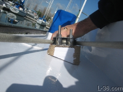
The work in process design
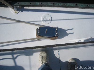
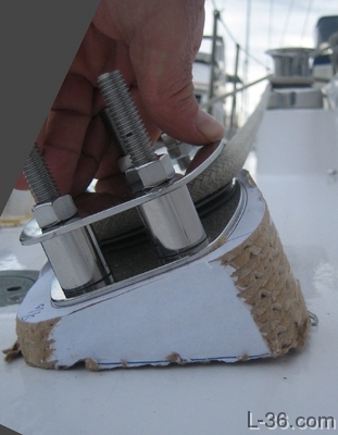
Here are three pictures of the prototype pad:
Some observations on my design. The angles are 8 degrees into the winch and 2.2 degrees into the mid track car position. I am using one design for both port and starboard. This causes a very small deviation from the 8 degrees and is true within 1 degree for the lead in angle into the foot block. This variation is due to the fact that the lead in to the winch is always on the port side of the winch.
The design parameters, other than the lead in angle, are that the lowest point on the block be about 1/2 inch and that the longest bolt required be less than 4.5 inches. The lowest pad height is 0.52 in the design and the bolt 4.47 allowing 2.23 for the deck, block, nut,and washer.
Right now it looks like the lead in angle for the car to foot-block is within +-1.5 degrees of true. The block can take about +-5 degrees of offset from true so this should be fine. Right now I need to take more careful measurements before finalizing the design and cutting my block of teak.
A note on the teak. I bought a block of teak 7.5x4.25x3.75 I can make one angular cut down the middle and get both the port and starboard piece out of it. The thickness of block required is the sum of the largest and smallest corner depths as you then get mirror image pieces that will work with the mirror image requirements of the port and starboard pads.
2/3/2008
Update: 2/23/2008
After taking more careful measurements I found that with the design approach I was taking, as the car moved on the track, I would get up to about 4 degrees of error. High when the car was close to the block, no error in the middle, and low when the car was far away. What I did was flatten the block some so that there was a 2 1/2 degree error for the nominal lead in to the winch. This caused the alignment to be better when the cars were at their extreme positions on the track. I set it up so that the error with the car at the extreme was about the same as the maximum error for the winch. I hard coded the critical points on the calculation page. These numbers can be figured with the rest of the sheet, but I wanted to read them out all at once.
The way I made the change was to lower the point on the plane for the winch to 6 inches. This has the added advantage of making the minimum standoff higher (for where I wanted to mount the block) and the maximum bolt length required shorter so things will fit better. It also made the angle of the bolts through the deck 11 degrees so the wedge required under the washers isn't as extreme.
This is my final design:CLICK HERE FOR FINAL DESIGN
I made a prototype out of wood which was useful for showing me how to make the final one. Lots of sub optimum fabrication methods will be avoided as I tried them all on these prototypes.
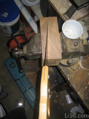
Cutting two blocks from one piece of wood
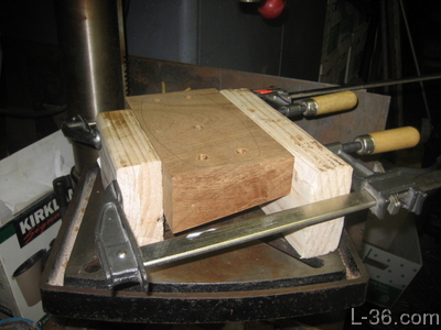
Set-up to drill holes -- done before rounding edges
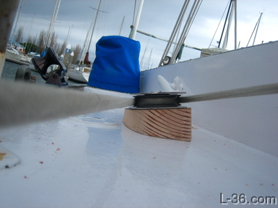
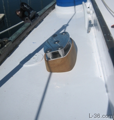
Finished Turning Block
Allen Edwards
NOTICE: Some pages have affiliate links to Amazon. As an Amazon Associate, I earn from qualifying purchases. Please read website Cookie, Privacy, and Disclamers by clicking HERE. To contact me click HERE. For my YouTube page click HERE