Using Autodesk Eagle and PCBway PC Fab By Allen Edwards
Introduction
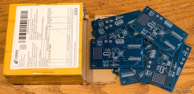
If you can draw a schematic, you can get professional quality PC Boards made for your boat projects for next to nothing. In fact, I just got a board back in two weeks for $14 total delivered and I got 10 boards for that. Completely custom and all done with easy to use free software. The fab shop I will recommend is fabulous, does a great job at a more than reasonable price and they do it fast. There is no reason to have any point to point wired boards on your boat any longer and no reason not to build that project you have always dreamed about. This article will take you through all the steps, point you to what you need, and I bet you will even have fun doing it. I did a simple design of a board that will take a WiFi or NMEA-0182 input from the instrument processor and drive a LCD or NMEA display. I will show you all the steps and you can download the design so you can play with an example. So let's get started.
Overview
Assuming you are starting with a design, the steps to turn that design into a finished PCB are pretty straight forward.
Creat your design
Get a copy of Eagle (PC board layout software)
Why Eagle?
Learn how to use it
Enter your schematic
Create the board layout
Check your work
Create a Gerber File
Check the Gerber
Order Boards
Upload Gerber File
Order Review
Payment
Monitor Status in Production
Track shipment
Receive your package
Things I should have done
Create your design
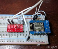
I won't spend much time here but will say be familiar with these vendors: Sparkfun, Adafruit, Amazon, Mouser, DigiKey, and AliExpress. Get breakout boards and wire up your project on a standard breadboard. Once it is working, it is time to get a professional PC Board made. How to do that is what this article is about. It is as simple as 1-2-3. Enter your schematic into the layout software, create the physical layout, and get the boards made.
Get a copy of Eagle
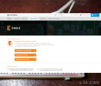
Eagle was purchased by Autodesk in June of 2016 by purchasing CadSoft. There are levels of Eagle. The Free one will do a board the size of a large breadboard, 6.25" x 2" (80 square cm). I have done larger boards as long as the traces don't occupy more than 80 square cm. It is limited to two layers. There are two steps above that but I have not had need for anything beyond the free one. The others are by subscription. The next version up is $15 a month. You can download it HERE.
Why Eagle
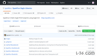
My first PC Board experience was having a friend of a friend lay out a board for me. He used a PC layout tool called CircuitMaker that was very difficult to use, hard to learn, and basically I was unable to do the second layout. Eagle on the other hand is well supported in the hobby community. One of the issues in PC Design is creating parts. Groups of parts are called libraries. A part has a schematic, a package, and an interconnect. While you can make your own parts, it is better not to have to. Many vendors have libraries of parts for Eagle. Vendors like SparkFun and Adafruit will supply Eagle files for the products they sell and libraries of these parts. Parts vendors usually supply Eagle libraries for the parts they sell -- I particularly like the SparkFun Eagle Library. Download HERE. There are YouTube videos on all aspects of how to use Eagle. Basically, it is the product to use.
Learn how to use Eagle
SparkFun has extensive tutorials on using Eagle for every step from installing it to sending Gerber files. HERE is a link. What I recommend is a series of three YouTube videos by Jeremy Blum. They are about 30 minutes each and really walk you through the process. They have some plugs for Element 14 as they owned Eagle for some time but those do not get in the way. Just Google "Eagle Tutorial" and hit Video and they are the first three hits.
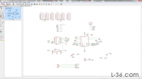
Enter your schematic
This article will follow the progress of a design. It is a generally useful design having two RS-232 (nema-0183) ports and a port to drive two LCD displays as well as an ESP-8266 which is an 80MHz CPU with a full WiFi stack. It is a pretty amazing part that costs about $3. It is an excellent choice for small designs even if you don't need the WiFi. HERE is a larger version or you can click on any of the small icons and see a larger version. The 6 rows of connectors on the top will be a breadboard area on the finished board in case I want to add some circuits. I am not sure this is portable but here (Download the file) is the schematic file. Feel free to download it and modify it to your needs. Get the board first so they will stay linked.
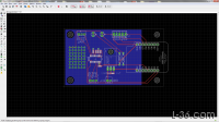
Create your board layout
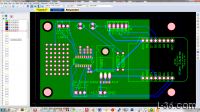
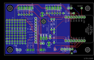
When you first create a schematic and open a board layout, you need to define your board outline. The parts will be randomly put below the layout. Drag them and place them on the board where you want. Note how lines cross as rotating the parts might make layout easier. You also might want to reassign pins to connectors to make things easier on the layout. I do not use the auto-router but give it a try if you want. I just keep pressing the ratsnest button so see where traces need to go. All this is explained by Jeremy in his tutorials.
HERE is a larger version if the layout. (Download the file)
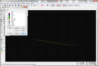
Check your work
Before you create your Gerber files, you need to do some checks. The first one is on the schematic. You should do an ERC as you go along but do one more now. Then on the board do two checks. First, click on the layer settings and turn off everything except unrouted traces and look for traces you missed. Then do a final DRC, which you should also do during the layout itself. I am embarrassed to admit that this sample board will come back with two missing traces because I did not run the ERC. It makes a function I do not use not work so it is not a big deal, but it is embarrassing nonetheless. HERE is a larger version where you can see the missing traces that showed up after I corrected the schematic.
Create a Gerber file
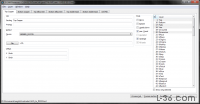
Use the CAM processor on Eagle to create the Gerber files. You can use one I modified from what Jeremy had if you want. There is also one on the SparkFun site and they may be the same. This file creates individual files for the top and bottom copper, solder mask, and silkscreen. These are all easily identified by the capital letters on the extensions. There is also a drill file indicated by .TXT extension. Put these files in a directory and zip them together. This will be your deliverable but first you need to check them as there are some differences between what you will see in the Gerber file and what you see in Eagle.
(Download the CAM file)
Check the Gerber
To check the Gerber files I recommend you view them using Pentalogic ViewMate, a free Gerber viewer. You have to register and follow the download instructions but it is free and works well. Pay particular attention to the silkscreen. One point to consider, if you are labelling the pin-outs on a connector, you will be better using a separate label for each pin rather than stringing them along in one label with spaces. The font sizes in Eagle are slightly different than what I see in Viewmate. Viewmate matches the final board.
Order PC Boards
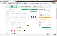
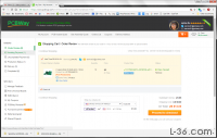
I highly recommend PCBWay. There are other vendors but I cannot vouch for them as I have not tried them. I have done 8 orders with them, several for multiple designs. In all cases the quality was excellent and the processing time mind boggling fast. I don't know how they do it. The first 6 orders I did were all delivered by DHL and the average time from when I sent in the Gerber file to parts at my door was one week. But for this article, I wanted to try the economy layout and shipping. They have a special of $5 for up to 10 2 layer boards if they are under 100mm x 100mm. Ordering is easy. Just go to the Online Quote page and enter the size of the board and enter 5 as the quantity. Click OK on the "HASL" question below the Surface Finish. I have always left all the options as the default except on this last board I asked for blue solder mask. Then click on "Calculate". Then click on the Price Comparison Matrix and make your decision on how many to get based on the cost. I had one small board that was so inexpensive I ordered 40 instead of the 20 I ordered for the rest of the boards in the order but at an additional $5 for twice as many boards, I could not resist. Finally, click "Add to Cart". Don't worry, you don't pay until they review and accept your order.
Upload Gerber File
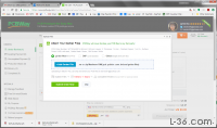
Before you submit your order you should upload the Gerber File. Just click on +Gerber File and point to your zip file. Then click on Submit Order. This puts your order into a review at their end. I am sure they want to make sure there is nothing strange and that the size agrees with what you said. They have greatly sped up the review process from the time of my first order.
Order Review
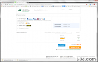
After they check your order and approve it, you will see the final price. Here you can change the delivery option which will affect the price and the time it takes to get your order. DHL is very fast. The order will clear customs in the US before it leaves China. They take 2-3 days. E-packet is half the cost and takes 10-15 days. My order build time was 2 days under the estimate and shipped on 1/5 and I got it on 1/16. It would have been faster except there was a holiday on 1/15.
Payment
I pay with PayPal and use a credit card. There may be other options. I am not sure as I always use PayPal.
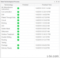
Monitor Status in Production
It is amazing how fast the boards are made. They never sleep. This board was done in a day and a half. There always seems to be a delay from when the board is done until it shows as shipped. Even the order that took just 5 days from Gerber to doorstep sat for a full day between processing complete until it showed that it had shipped. The point is, that is not a cause for concern. I imagine that it's the time to get it over to the shipper or some other processing anomaly that shows up as a delay.
Track shipment
Tracking takes a few days to show up in the ems system but shows up pretty quickly if you pick DHL. Note that with DHL, you can pre-sign and have the package left at your door. For some reason, they will not put the package in the mail box even if it is not a US Postal Service mail box. But I did have them leave the package at the door once when they surprised me with the 5 day TAT and I was out of town. The package was there when I returned. A note on the EMS tracking system. Copy and paste the tracking number into the EMS website and then enter the 6 digit verification code they print on that page. I guess that is their anti-robot security feature.
One thing that might be useful. If you use EMS, when the package arrives in the US, you will see a code like USUSSFOF. The USUS seems to be the United States and SFO is San Francisco, in other words the airport code. Not from PCBway, but from other vendors I have had my packages land at JFK which is about as far as you can be from me. They seem to land anywhere and then are given to the poor USPS to deliver at a loss. I don't want to get political here but this EMS shipping and much of what is going on here doesn't seem fair to US companies. How can anyone complete with what I have described here? On the other hand, how can you resist taking advantage of what is available?
Receive your package
No review would be complete without the unboxing video so here it is.
Things I should have done
I should call this the checklist I wish I had before I did the board. Here it is for your consideration.
Label pins on connectors
Add test points
Have several ground pins to attach voltmeter and scope.
Surface mount parts are for automation. Use through hole.
Make a breadboard area just in case. Add power and ground to some of the pins.
Modify packages if they don't fit the actual parts. T-220 in my case.
The new WeMos D1 Mini Rx pin doesn't always work. I would suggest using one of the clones with the can. WAVGAT for example.
Install a couple of LEDs to show power and maybe blink one for activity.
Bring more things out to a connector just in case.
Make all IO pins accessible for modifications.
Connect some of your breadboard areas together so you can connect components up without wires.
Although this was just basically a test board for this article, I got a bit excited about turning it into a general purpose board that has WiFi and one or two RS-232 (NMEA) port plus some indicators, can drive an LCD display and has a nice little breadboard area. While I was waiting for this board to arrive, I designed a new one. I decided to go back to my SparkFun MAX-3232 breakout boards as I was less excited about surface mount and the extra $1 to get the SparkFun boards seemed worth not having to go to the trouble. It is very simple to just solder some headers and be able to reuse the breakout boards. I may never build this new version as in reality the one I just got back will work fine for what I want.
Conclusion
I hope you enjoyed this article. Please feel free to email me if you have any questions.
NOTICE: Some pages have affiliate links to Amazon. As an Amazon Associate, I earn from qualifying purchases.
Please read website Cookie, Privacy, and Disclamers by clicking HERE.
To contact me click HERE. For my YouTube page click HERE
