No Shackle Toggle Halyard
By Allen Edwards
UPDATE
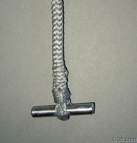
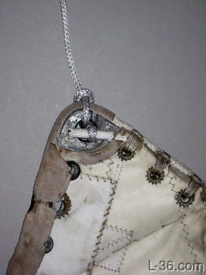
To the left is the latest version and one I prefer over the ones in the rest of this article although either would work. To make this one I used 1 3/4 inch of 5/16 aluminum rod and drilled two holes in it just a size above 1/16 diameter. I then used "Lash-it" through the holes to hold the eye splice in place then lock stitched the splice with the Lash-it. Finally I whipped it and tied off the ends. Aligning the holes as shown perpendicular to the axis of the halyard makes almost no difference in the strength of the rod. If they were aligned parallel to the halyard, it would cut the strength. I like the cleaner nature of this version, plus it is easy to inspect as nothing is covered. That said, they both work.
Overview
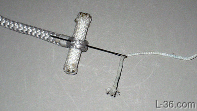
This article shows how to make a simple extremely light and easy to use no shackle integrated toggle for attaching a halyard to the mainsail. This method works with HM line such as Amsteel. There are several articles elsewhere on the site that show how to make Amsteel to Line halyards. This article is the finishing touch.The picture below shows a finished halyard end with a toggle stitched to an eye in the Amsteel. The toggle is an aluminum 8mm rod covered with some 11mm spectra tubular webbing although you can use the outer braid of some 5/16 or 3/8 double braid.
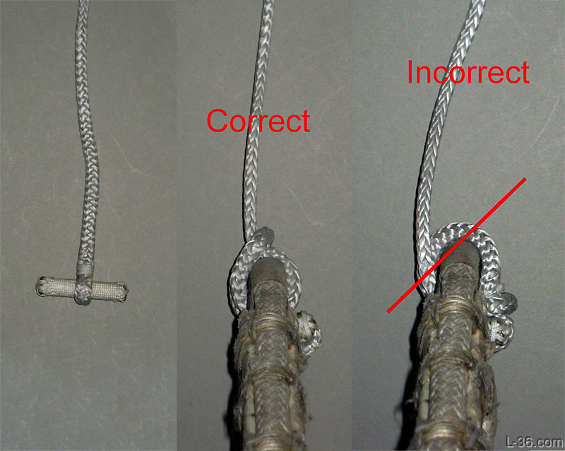
The second picture shows how to rig the halyard so that it pulls up on the centerline of the headboard. There is a little trick that makes this easy. The final picture shows the incorrect but easier to understand way to rig the halyard. It is incorrect because it puts a twist in the head board. I show this because there are some vendors promoting this way of attaching their dog bones. Maybe a dog bone needs to be rigged this way to prevent if from coming out, but it is not correct in the yachting since of the word.
My thanks to L-36.com reader Bob Schaefer for the key idea for this, the email exchange of several versions, and the trick that makes this all work.
How to Rig
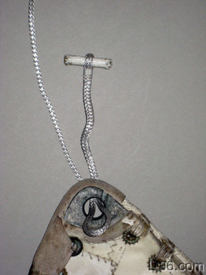
Make a loop in the bright and pass it through the headboard.
Pass the toggle through the loop. At some point you will want to make a mark on the bright where it lines up with the loop as this makes the next step easy but at first, just leave a fair amount of line as shown.
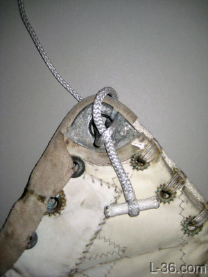
Now pull on the standing part. This will bring the loop back through the headboard opening and pull the line near the toggle with it. This is the trick that forms the nice loop on top of the headboard so that the force from the standing part is right over the top of the sail. You can work this a bit to make it line up perfectly. Then reverse the last step and note where the line and the eye line up and mark it for reference in the future. This eliminates the need to make any adjustment after you do this step.
Storage

Use a double soft shackle or a line shackle to secure the halyard to wherever you like to lead the halyard to when not in use.
How to Make it
There isn't any one right way to make these other than to take some metal rod that is the appropriate size and secure it inside some tubular webbing, some twelve strand, or the outer braid of some double braid. I have done all three and just think the tubular webbing looks the best.
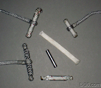
In this picture, you can see a variety of methods. Some just whip the ends like a sausage, one makes a couple of small end splices, and of course the one with the tubular webbing. An aluminum rod and some unused webbing is shown in the center.
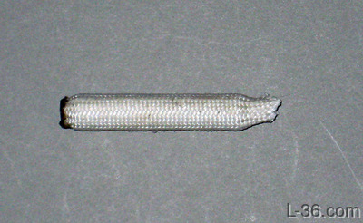
Here I inserted the rod into the webbing and cut the ends of the webbing off about 1/4 inch from the ends of rod. I used a lighter to melt the webbing, pressing it together into a ball on the ends and pressing it flat with the metal end of the lighter. This formed a secure end and captures the rod. On a previous version, I stitched over the ends to make sure the rod was secure but this method looks more than secure enough.
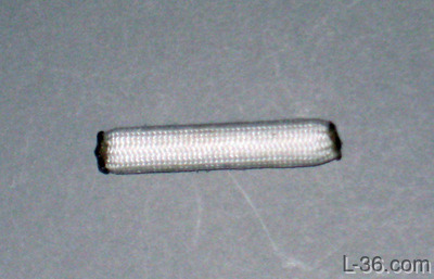
Here is the finished covered rod. I made the rod about twice as long as the opening in the halyard. That is more than long enough. The next step is just to make a very small eye splice in the end of the halyard and pulling it tight around the toggle. Lock stitch the eye splice and whip the neck of the eye. The whipping on the neck keeps the toggle at right angles to the halyard, which further improves the security in keeping the toggle from being able to go through the hole.
Finally, stitch the eye to the covered toggle. Run the needle through the eye and down against the metal so that the needle goes through the toggle cover. Then move down the eye a bit and stitch back toward the initial opening. Do this several times so that the eye is securely stitched to the toggle.
Strength
I posted this on Spar Talk:
I am going to show my work as I am unsure of it. Perhaps someone can verify what I have done or correct it.
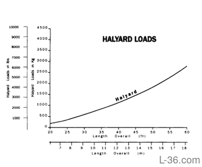
The question is, how large a toggle do you need to hold the halyard per the technique shown HERE and discussed above. I am going to solve this for 5/32 Amsteel which is 4000 pounds breaking strength and assume that I want to be able to hold that load at breaking strength. Finding halyard load is not easy. The chart in the back of Brion's book (page 372) for a 35 foot boat says 800 pounds. That would be a 5:1 safety factor, which sounds fine so I went with that.
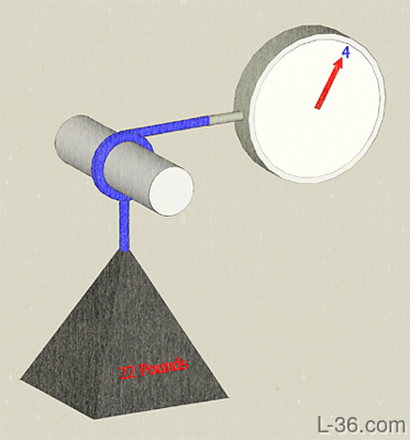
The way the line is led is not exactly a knot but it does offer some stress relief to the toggle. I tested that around a very smooth post which for sure would be worst case compared to the friction of a head board. It took only 4 pounds to hold a 22 pound test weight. Thus the 4000 pound load could be held with 727 pounds on the toggle.
I assume a .75 inch opening in the headboard and 727 pounds gives a bending moment of 51 inch pounds per this formula ( w * l^2 ) / 8 .
Using a pin of radius r the load on the outer most point r from the center of the pin is 51 * r / J where J is the moment of inertia of a circle which is ( pi * r^4 ) / 2
Combining these the maximum stress as 32 / r^3. Aluminum is 35,000 psi which says r minimum is .097. That is a diameter of .194.
Oak is 7440psi so r is .16 and diameter is .325 or just over 5/16. Being wood, perhaps an additional safety factor would be appropriate and a 3/8 to 1/2 inch toggle would give that. Wood has the additional issue that the surface might crush and I did not analyze that.
I would love for someone to verify these numbers and I would encourage nobody to use them or rely on them until that happens.
UPDATE: Looking at the numbers for the moment of intertia of a circle about a line through the center the formula is
( pi * r^4 )/ 4 and not what I said above. That changes the minimum diameter to 1/4 inch. Another reason for someone to check these numbers. but I am going to use 5/16 as it just looks like the right size.
NOTICE: Some pages have affiliate links to Amazon. As an Amazon Associate, I earn from qualifying purchases. Please read website Cookie, Privacy, and Disclamers by clicking HERE. To contact me click HERE. For my YouTube page click HERE