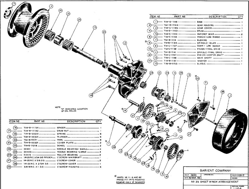
Winch Service Manual for Barient No. 35 - 1969
1. Using universal deck plate key, remove drum nut (#17) from top of drum (#4).
2. Remove drum (#4) from rest of assembly, watching that two roller bearings (#25) and sleeve (#15) do not drop out and become damaged.
3. Remove two roller bearings (#25) and sleeve (#15) from gear housing shaft (#25).
4. Using 5/16" allen wrench, remove six cap screws (#29) from gear housing (#2).
5. Insert lock-in handle into main shaft (#13) on gear housing (#2) and lock handle.
6. Using lock-in handle, remove gear housing (#2) from base (#1).
7. Lay gear housing on its side.
8. Using 3/16" allen wrench, remove two cap screws (#27) and cap screw (#28), which holds gear cover (#3) to gear housing, from gear housing (#2).
9. Remove gear cover (#3) from gear housing (#2). This is a pressed fit onto dowel pins and should be worked off evenly around the diameter with a screwdriver.
10. Using box wrench, remove cap screw (#26) from center shaft pinion (#12). (Insert winch handle at other end of shaft to prevent it from rotating.)
11. Remove washer (#14) from under cap screw (#26).
12. Remove main shaft (#13) and large needle bearing (#24) from center pinion (#12).
13. Remove center shaft pinion (#12) and another large needle bearing (#24) from gear housing (#2).
14. Remove all remaining gears together.
15. Remove final drive pinion (#10) from low range gear (#9).
16. Remove two small needle bearings from low range gear (#9).
17. Remove ratchet gear (#5) from low range gear (#9).
18. Remove four pawls (#20), four pawl springs (#18), and four plung ers (#19) from low range gear (#9).
19. Remove another ratchet gear (#5) from low range pinion (#6).
20. Remove two pawls (#20), four pawi springs (#18) and two plungers (#19) from low range pinion (#6).
21. Wash all pawl, springs, plungers, bearings and all other parts that should require cleaning.
22. Oil plunger pockets in low range pinion (#6) and low range gear (#9).
23. Assemble four pawls (#20), four pawl springs (#18), and four plungers (#19) onto low range gear (#9).
24. Assemble two pawls (#20), two pawl springs (#18), and two plun gers (#19) onto low range pinion (#6).
25. Grease all bearings.
26. Assemble two small needle bearings (#23) into low range gear (#9).
27. Assemble final drive pinion (#10) onto low range gear (#9).
28. Assemble ratchet gear (#5) onto low range gear (#9).
29. Assemble two small needle bearings (#23) into low range pinion (#6).
30. Assemble ratchet gear (#5) onto low range pinion (#6).
31. Assemble cover plate (#21) to bottom of low range pinion (#6) with groove facing pawls.
32. Assemble low range pinion (#6) onto idler spindle (#8) and low range gear (#9), and final drive pinion (#10) onto final drive spindle (#11). Roth pinions have to be placed on spindles simultaneously.
33. Assemble cover (#21) onto low range gear (#9) with groove facing pawls.
34. Assemble two large needle bearings (#24) into gear housing (#2).
35. Assemble main shaft (#13) into gear housing (#2).
36. Assemble center shaft pinion (#12) onto gear housing (#2).
37. Shove main shaft (#13) into center shaft pinion (#12).
38. Assemble washer (#14) onto cap screw (#26).
39. Assemble cap screw (#26) to bottom of main shaft (#13) and tighten with allen wrench.
40. Assemble housing (#7) onto idler spindle (#8).
41. Assemble large needle bearing (#24) into center shaft pinion (#12).
42. Assemble gear cover (#3) onto gear housing (#2).
43. Assemble two cap screws (#27) through gear cover (#3) and tighten with 3/16" allen wrench.
44. Assemble spacer (#16) and cap screw (#28) to gear cover (#3). Tighten with allen wrench.
45. Insert lock-in handle into top of main shaft (#13) and lock in place.
46. Using lock-in handle, place gear housing (#2) onto base (#1) not ing that notches on base (#1) will fit gear housing (#2) only one way.
47. Secure gear housing (#2) to base (#1) using six cap screws (#29) and tighten with 5/16" allen wrench.
48. Assemble roller bearing (#25), sleeve (#15), and roller bearing (#25), in this order, onto gear housing (#2).
49. Assemble drum (#4) over gear housing (#2) and onto base (#1).
50. Assemble drum nut (#17) over top of drum (#1) and tighten with universal deck plate key.
NOTICE: Some pages have affiliate links to Amazon. As an Amazon Associate, I earn from qualifying purchases. Please read website Cookie, Privacy, and Disclamers by clicking HERE. To contact me click HERE. For my YouTube page click HERE